STRUCTURAL GRAPHIC REPRESENTATION METHODS FOR WEFT KNITTED FABRICS
Constanta Comandar, Luminita Ciobanu, Ancuţa Tulbure
Abstract
The structure of knitted fabrics is given by the position of its elements within the technical system of the knitted fabric.
The graphic representation of a fabric structure means to draw the yarn geometry and the shape of structural elements (normal stitches, stitches with modified geometry and yarns) using the same colour or different ones.
Apart from the yarns geometry, a graphic representation can be used to define the pattern and the pattern dimensions, some technological indications and structural effects in the fabric.
1. Introduction
Different methods are used for the graphic representation of knitted fabrics. The following ones are in use for weft knitted fabrics (Figure 1):
· structural representation (analytical);
· representation using the yarn path;
· representation using knitting notations;
· representation of pattern aspect.
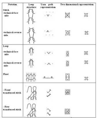
Figure 1. Methods of fabric representation
1. Structural (analytical) representation accurately reproduces the yarn geometry within the knitted fabric. The structural representation can be theoretical and real.
In the case of the theoretical structural representation the stitch arms are considered to be straight segments, while the needle and sinker loops are half circles. The stitch elements are drawn according to the evolution and fabric aspect.
The structural representation is simplified by using special paper with half circles drawn on it as needle loops. Figure 2.a-c exemplifies the theoretical structural representation of an interlock fabric. Due to the specific position where the front stitches cover the rear ones, the front stitches were enhanced while the rear stitches were narrowed.
a) b) c)
Figure 2. Example of structural representation
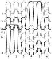
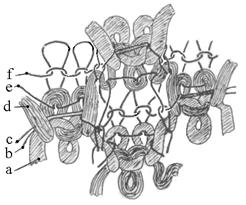
In the case of real structural representation, the yarn and stitch geometry is presented in relax state; the yarn is represented with a certain diameter and not a simple line. In comparison with the theoretical method, the real method of representation is far more complicated and complex. The structural elements present specific geometries depending on: structural characteristics, structural parameters, raw material characteristics and finishing process.
In order to represent the stitch geometry the theoretical position is modified (vertical displacement of the stitches, inclined position of the sinker loops, inclination and/or rotation of the stitches), as exemplified in Figure 3. This type of representation is based on the fabric analysis, often using the microscope.
Figure 3. Real structural representation of 1x1 rib
The analytical representation is a time-consuming method, but it is the one presenting the most complete information regarding the fabric structure.
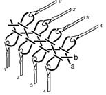
2. Representation using the yarn path presents the position of the yarn on the needles (Figure 4.a). The needles are represented as on the machine, using points (sometimes bars or lines). The method has the advantage of giving information on the knitting process (number of beds, relative needle position, the way the needles work).
|

|
a) |
b) |
Figura 4. Position of the yarn on the needles (a) and knitting sequence (b) |
In the literature, the method has two variants:
- One presenting a general view of the yarn on the needles, together with the old loops (Figure 4.b)
- Another one a simplified and quicker method, eliminating the old stitches. The disadvantage of the last method is that it suggests a crossing of the stitch arms that does not exist in reality.
The method can be considered symbolic because it does not correspond to the technical section of the stitch row.
3. Representation using notations uses signs for the structural elements. The method has many variants, the one used in our country being based on the following notations:
x = front stitch; o = rear stitch
The literature recommends other notations methods such as Proussa and R.G.T. (Raprezentazione Grafica dei Tessuti).
The R.G.T. method uses the following main notations:
½ = front stitch; - = rear stitch;
· = floating; ° = loop
3. Structural representation using CAD systems
The programming stations of the modern knitting machines present the possibility of structural representation of the knitted fabric while designing it. The fabric structure is simulated and the yarn is drawn considering its diameter. Figure 5 illustrates the methods of fabric representation used on Stoll programming station.
 |
|
Figure 5. Fabric representation on STOLL programming station |
Each company producing electronic knitting machines has its own CAD system. For example, Shima Seiki uses colour codes while Stoll uses notations and Fabric View.
3. Representation methods for fabric patterns and effects
Apart the three representation methods commonly used, the fabric pattern/effect can also be represented with different methods.
In the case of knitted fabrics with colour patterns, as well as jacquard patterns, the representation can include only the fabric front aspect, eliminating the rear part without a pattern.
A squared paper is used and each square contains a colour corresponding to the pattern. In order to have more information regarding the fabric structure, the method must be completed with at least one of the common methods but only for a significant part of the pattern. Each square contains the “x” notation (front stitch) or is filled with the corresponding colour.
The calculus of the stitch width and height is also important for the fabric design. Their ratio defines the correspondence between the designed fabric and the produced one. If this ratio is not taken into consideration, differences will appear between the designed and the real pattern shape and effect. This is why the pattern design ending requires defining the stitch dimensions.
The following situations are identified when comparing the stitch height/width:
- C = 1 Þ B=A; the designed pattern is similar to the pattern produced on the machine;
- C ¹ 1. In order to respect the ratio between the designed and the knitted pattern, the pattern height is multiplied with the value of the stitch density ratio C.
- C > 1 Þ B > A; the stitch surface is a rectangle with a smaller base
- C < 1 Þ B < A; the stitch surface is a rectangle with a higher base.
The problem is solved when designing fabrics using CAD systems that simplify the pattern definition through the stitch density ratio.
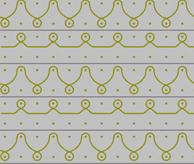
Figures 6 - 9 illustrate examples of fabric representation using notations, defining the pattern area. The tuck stitches are marked in Figure 6 and the increase in stitch width is evident. Figure 7 presents the real structural representation based on microscope analysis.
Figure 8.c presents an example where the wale inclination produced using stitch transfer (Figure 8.a) is shown in the structural representation illustrated in Figure 8.b.
 |
|
Figure 6. Effect representation using notations |
Figure 7. Structural representation based on microscope analysis |
|
 a) a)
 b) b)
|
 c) c)
|
|
|
Figure 8. 1:1 rib fabrics with inclined wales |
|
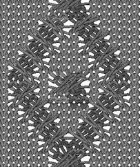
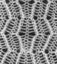
Figure 9 presents a rib fabric with tuck stitches, produced using yarns of different count. The first two representations do not suggest the effects obtained through the presence of thicker yarns, as fabric picture shows. This is obtained only by using the real structural representation.
|
|
|
|
Figure 9. Representations of a jersey fabric with tuck stitches produced using different counts |
5. Conclusions
The representation of weft knitted fabrics cover a large range of methods, varying from country to country or being common. Structural representation of knitted fabrics allows to define completly the yarn geometry while the yarn path representation shows the knitting sequence.
All weft electronic knitting machines use programming stations. The generalisation of CAD systems determined the apparition of knitting softwares, including 2D representation that can be used for any type of machines.
Acknowledgements
This paper is published within the frame of research project PNII ID 589, sponsored by the the Romanian Ministery of Education, Research and Youth, for which the authors recognise financial authority.
Reference List
- Comandar, C. - “Structura şi proiectarea tricoturilor – Tricoturi din bătătură”, editura Cermi, Iaşi, 1998
- *** - DIN 62050-1, “Maschenstoffe – Gestricke und Kuliergewirke, Grundbegriffe und Bindungen”
- *** - ISO/DIS 23606, “Textiles –Knitted fabrics – Representation and patern design”
.